6. 时序逻辑1:触发器[英]
本文最后更新于 2025年9月1日 上午
Sequential Logic 1: Types of Flip-Flops
Sequential logic circuit
A sequential logic system with feedback connections from the output called internal inputs.
User cannot control the internal inputs.
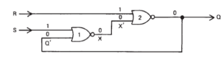
For example:
\[Q=\overline{R+\overline{S+Q'}}\]
- \(Q'\) is the feedback (previous output).
- \(Q\) is the current output, in the following calculation, this \(Q\) will be back to \(Q'\).
- \(S\) and \(R\) the external inputs.
If the inputs combination can cause the never-changed output(\(Q=Q'\)), the output/combination/circuit is stable.
In Kmap the stable combination is first numbered and then uncircled and the unstable combination will be marked with the number corresponding to its final stable combination but uncircled.
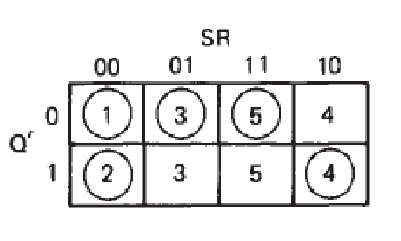
But for some combinations when \(Q≠Q'\), they can never achieve the stable state.
Fundamental Types of Flip-Flops (触发器)
SRFF (Set-Reset Flip-Flop)(RS触发器)
Set and reset functions are introduced to this kind of system.
The transition table defines the data transition from present state to next state(\(Q_t\rightarrow Q_{t+dt}\)).
SRFF can reduce the bounce in circuit.
In SRFF, the truth table considering with feedback \(Q'\) in previous time as input is:
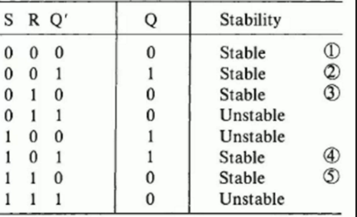
(Note that only when \(Q=Q'\), the system will become stable.)
By such a table, a more condenced table can be concluded:
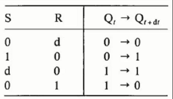
Rules
By exploring on above tables, the rules of SRFF can be found:
- If Set is on(the value is 1),the result(Q) will be turned to 1.
- If Reset is on(the value is 1), the result(Q) will be turned to 0.
- \(SR=11\) (when previos input is 00) can cause hazard, the practical result will not same with the truth table.
Limitations
The current change from one state to another (set-reset flip-flop, SRFF) practically is not simultaneous which can cause hazard.
Example:
\(11→00\), \(11→10/01(hazard)→101/010\).
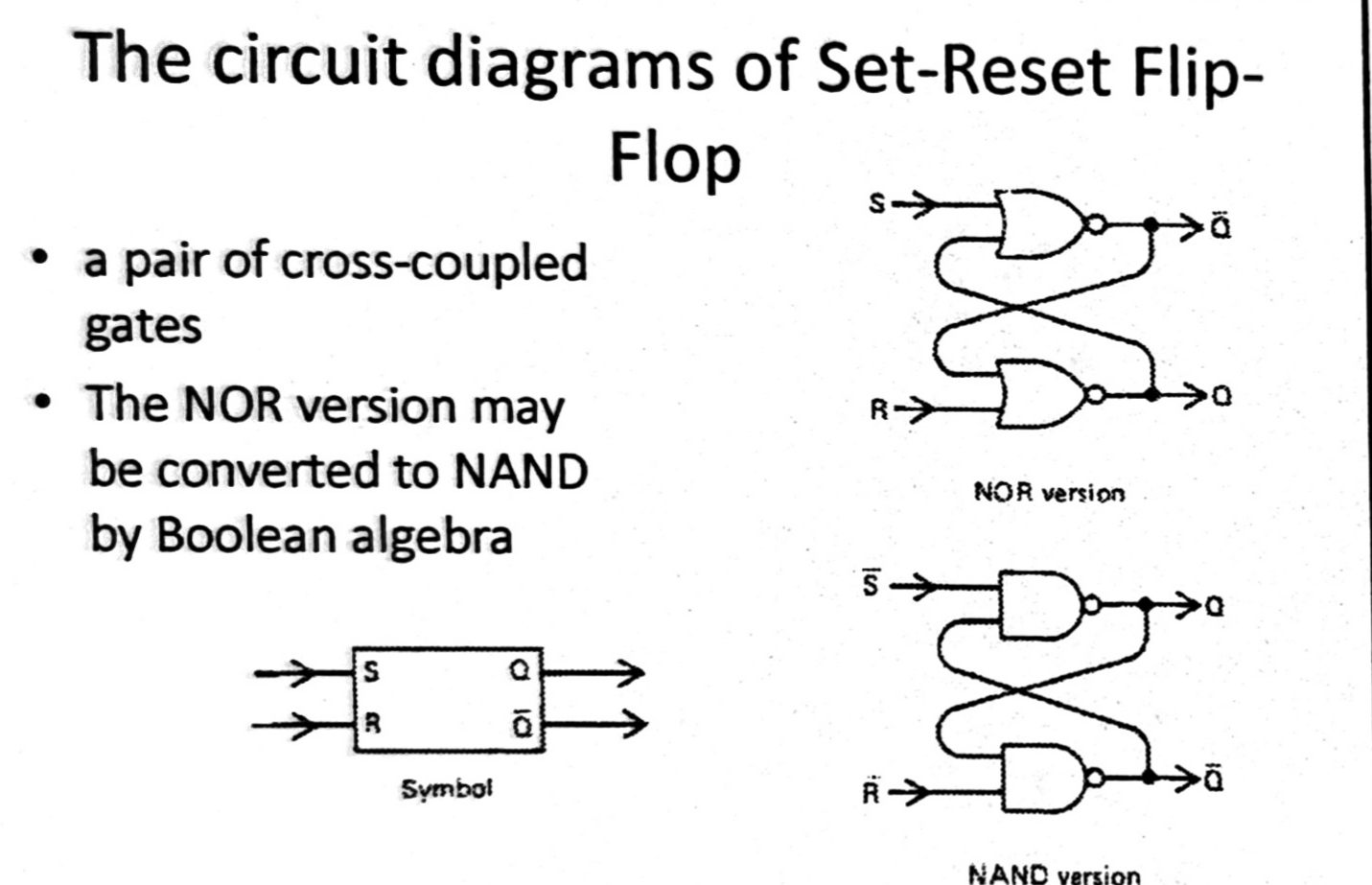
Variants of SRFF
The NAND/NOR only version SRFF(Also called SR Latch) is shown as below:
JKFF (JK Flip-Flop)(JK触发器)
Structure
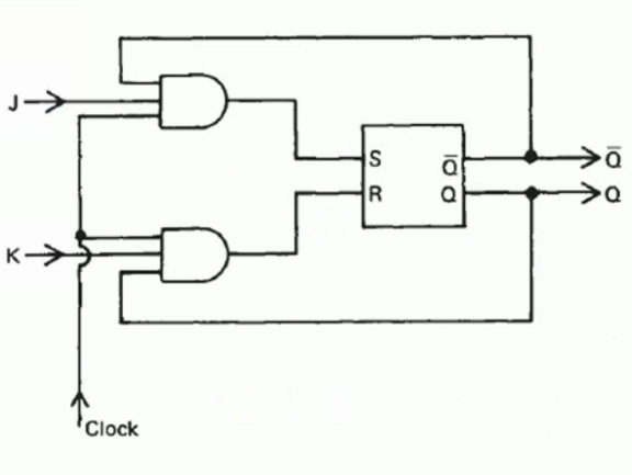
- \(K\) is an external input ANDed with a clock and \(\overline{Q}\) to \(R\).
- \(J\) is an external input ANDed with a clock and \(Q\) to Set.
- Clock pulses (时钟脉冲,\(clk\)) is introduced to this kind of SRFF system to control whether the inputs will be work aiming at prevent the Hazard. If clock is 0, the inputs are 0, the output will be not change.
The benefits of such kind of design:
In this way, we can firstly set \(clk=0\) and wait the input signal \(JK\) to be stable, then let \(clk=1\) to input stable \(JK\) into \(SR\). So that the unstable input signal would not affect on the system.
From the seconds between the change from 11 to 00, the clock value is change to 1 to let the result(\(Q\)) is d to prevent the effect of value 10/01.
Example: \(11→11/01\)(clock closed(0),the output will not change)→00Because \(Q\) and \(Q'\) are connected to \(J\) and \(K\) separately, \(SR\) (the result of AND gates) can not be 11.
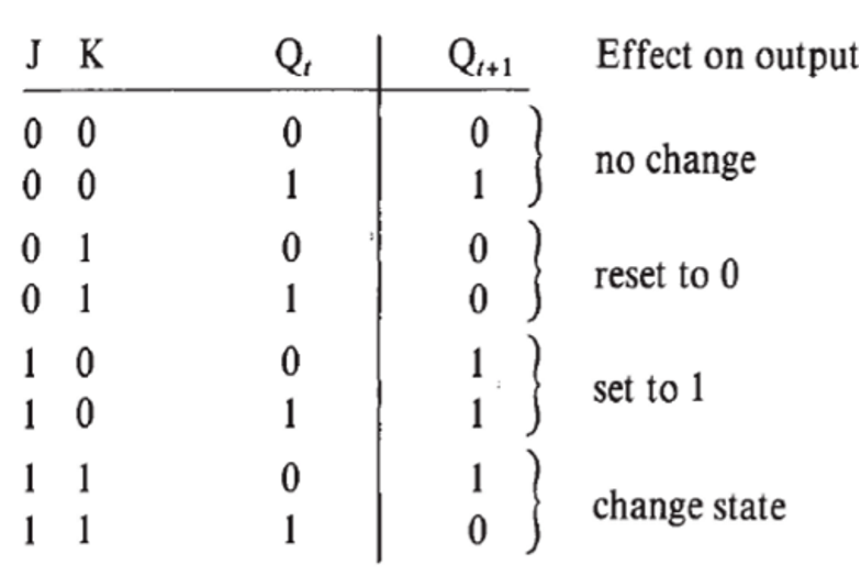
The truth table is shown as follows:
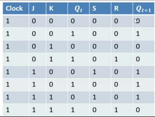
This truth table can be summerized as a transition state table:
| \(J\) | \(K\) | \(Q_t→Q_{t+1}\) |
|---|---|---|
| 0 | d | 0→0 |
| 1 | d | 0→1 |
| d | 0 | 1→1 |
| d | 1 | 1→0 |
The characteristics are:
- \(J\) has the same function with \(S\).
- \(K\) has the same function with \(R\).
- When \(JK=11\), the value is inversed.
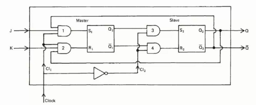
The Master-Slave JKFF(主从JK触发器)
One problem of original JKFF is that, when a bunch of signals are inputted into JKFF together, there may be a issue that JKFF cannot handle all of the inputs. In this way, we cannot deduce the input according to the output.
A master-slave JKFF uses 2 SRFFs(master and slave), together with input gating logic.
When clock is 1, gate 1 and 2 are opened to receive \(J\),\(K\), and gate 3 and 4 are closed. And then waiting clock changes to 0, gate 3,4 are opened to receive \(Q_1\) and \(Q_1'\) and gate 1 and 2 are closed.
In such a kind of ways, the input data sequence is produced one by one, so that one input in a \(clk\) time corresponding to a output. It is easily to see the output.
Fallen Edge Triggering (下降沿触发)
In addition, it can be oberved that for each time, only when the \(clk\) signal changing from 1 to 0, mast-slave JKFF will work according to the transition table of JKFF.
This kind of triggering is called fallen edge(\(1→0\)) triggering(下降沿触发).
TFF (Trigger Flip-Flop)(T触发器)
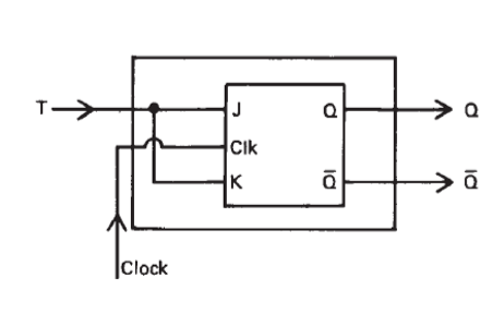
The asynchronous(异步) TFF
The inputs to the internal M-S JKFFs are connect permanently to 1 to \(J\),\(K\). Trigger is connected via clock line:
\[J=K=1\]
\[clock=T\] 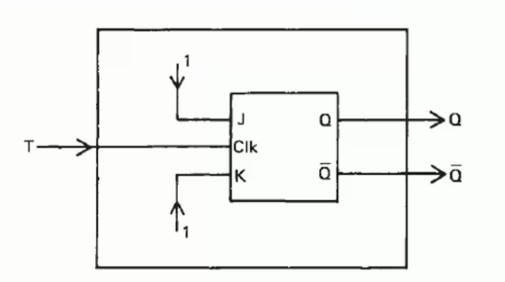
For a fallen edge(下降沿) of a clock waveform(\(T:1→0\)), TFF can inverse its value (\(0→1 or 1→0\)).
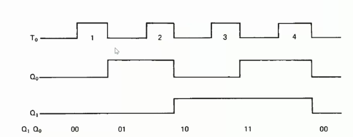
Example: 2-bit binary counter
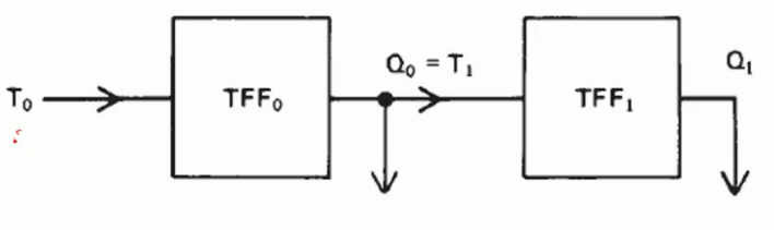
In this circuit, \(T_0\) is the outside waveform; The output of \(Q_0\) are fed to \(Q_1\).
The obervations are:
Synchronous TFF(同步T触发器)
In synchronous TFF, \(T\) is used to fed \(J\) and \(K\) simultaneously.
\[J=K=T\]
The transition state table of TFF is:
| \(T\) | \(Q_t→Q_{t+1}\) |
|---|---|
| 0 | 0→0 |
| 0 | 1→1 |
| 1 | 0→1 |
| 1 | 1→0 |
That can be concluded as:
- \(T=0\) keep the state.
- \(T=1\) change the state.
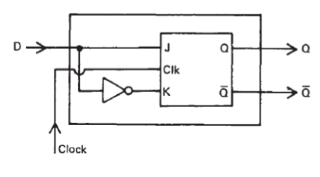
DFF (Delay Flip-Flop)(D触发器)
The single data \(D\) inputs in \(J\) and \(K\).
\[J=D\] \[K=\overline{D}\]
The transition state table of DFF is:
| \(D\) | \(Q_t→Q_{t+1}\) |
|---|---|
| 0 | 0→0 |
| 0 | 1→0 |
| 1 | 0→1 |
| 1 | 1→1 |
The behaviour of DFF is:
Whatever the \(Q_t\) is, the value of \(Q_{t+1}\) will always be \(D\).
If the clock is stopped(0), DFF will store its last input.
Example: Shift Register(寄存器)
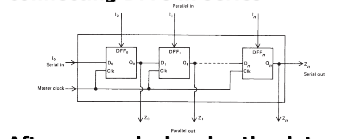
After every clock pulse the data stored in each flip-flop is shifted into its neighbor.(移位计算)
- Serial-in
The inputs are one-by-one inputted relying on time.
- Parallel-in
All the inputs are inputted together.
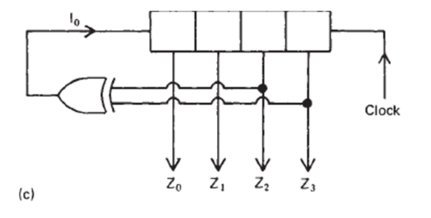
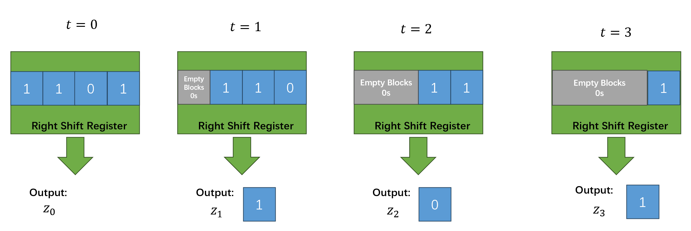
Example: For a 4-bit parallel-in and serial-out DFF combinational system:
when Inputs are 1101:
\[1101→0110→0011→0001\] \[z_0=0→z_1=1→z_2=0→z_3=1\]
Feedback shift registers
Normal feedback
The initial digit is \(Z_{n-1}\).
Example: for a 4-bit parallel-in feedback DFF combinational system, Inputs are 1101.
\[1011→1101→1110→0111→1011\] \[z_0=0→z_1=1→z_2=1→z_3=0→z_4=1\]
Feedback can be first operated.Inverted feedback
The result will be inverted to be the next inputs.
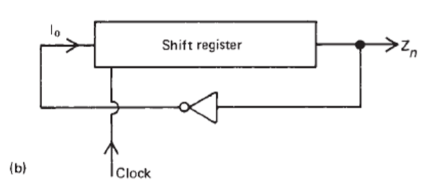
Example: inputs are 1011 (left shift) \[1011→0110→1101→1010→0100\]
Exclusive-or feedback